The DSVT intelligent heating and cooling control system coordinates heat source operation and individual room temperature regulation. A single controller can manage up to 12 independent zones.
The control algorithm takes into account the selected operating mode, valid sensor readings, zone target temperatures, configured hysteresis and additional control parameters.
This page describes the basic heating and cooling logic, including conventional hysteresis control for individual zones. Detailed explanations of thermal inertia, dew point control, weather-compensated operation and delayed heat source switching are provided in separate sections.
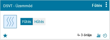
The first step is to select the appropriate system operating mode, followed by heating or cooling operation.
The system operating mode determines whether domestic hot water (DHW) production and buffer tank control are enabled alongside heating and cooling.
The heating/cooling selector determines which control algorithm DSVT uses.
In heating mode, the heating thermostat settings are applied. In cooling mode, the cooling thermostat settings are used.
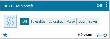
DSVT supports the coordinated control of two independent heat sources. Their operation can be configured using several different control modes.
For example, the first and second devices may be a heat pump and a gas boiler, although other compatible heating or cooling equipment can also be used.
The thermostat is switched off. DSVT turns off the heat sources and switching devices assigned to the corresponding heating or cooling operation.
The system operates exclusively with the first heat source.
The system operates exclusively with the second heat source.
In Switch mode, DSVT selects the first or second heat source according to the configured conditions.
The heating thermostat supports several switching criteria:
Depending on the selected control mode, the controller compares the current measured or calculated value with the corresponding threshold and selects the appropriate heat source.
This is particularly useful in systems combining a heat pump and a gas boiler, where switching may be intended to improve energy efficiency or accommodate the different operating ranges of the two heat sources.
Dual mode allows the second heat source to supplement the output of the first when additional heating or cooling capacity is required.
The conditions for activating the second heat source depend on the selected control mode. The decision can be based on indoor temperature, outdoor temperature, outdoor dew point or an appropriate electrical power threshold.
Indoor-temperature-based Dual control determines whether the second heat source is needed by considering the configured target temperature and the Dual temperature difference.
Simultaneous operation of two heat sources must only be used in hydraulic and electrical installations specifically designed to support it safely.
Saver mode combines the operating principles of Switch and Dual modes.
Based on indoor temperature, it can activate the second heat source when necessary, while outdoor temperature or outdoor dew point conditions can restrict operation of the first heat source.
This can be particularly beneficial in heat pump installations, where the primary heat source operates efficiently for most of the heating season but may require additional capacity or an alternative heat source under certain conditions.
DSVT also supports Switch and Dual operating modes associated with specific electrical power thresholds.
These modes operate using available energy metering data and configured power conditions. Properly configured energy monitoring is required.
Before performing temperature regulation, DSVT checks the readings from the configured indoor temperature sensors.
Invalid or timed-out sensor readings are excluded from valid measurements.
If no valid indoor temperature reading is available, the system reports an error and switches off the heating and cooling heat sources for safety reasons.
An outdoor temperature sensor is not mandatory for every operating mode, but valid outdoor data is required for control functions based on outdoor temperature or dew point.
If valid temperature data is unavailable for a particular zone, the controller applies its configured error handling rules and any available fallback temperature values.
DSVT collects the valid temperature readings from the configured zones.
If multiple valid temperature sensors are assigned to a zone, the controller calculates their average temperature.
DSVT calculates a central indoor temperature from the valid zone temperatures. This value is referred to as intemp in the plugin.
intemp = sum of valid zone temperatures / number of valid zones
This represents the calculated average temperature of the zones participating in control, rather than necessarily the temperature of the coldest room.
In addition to the average temperature, the system separately records the lowest and highest valid zone temperatures.
These values can be used for different temperature control functions.
DSVT maintains separate normal and economy target temperatures for heating and cooling in each zone.
Depending on the selected operating mode, the system determines the current target temperature for every zone.
The central heating target temperature is based on the highest current heating target value among the configured zones.
The calculated Fsetpoint may be further adjusted, for example through outdoor-temperature-dependent control or the use of surplus solar energy.
In cooling mode, the central target temperature is based on the lowest cooling target value among the configured zones.
The Hsetpoint may also be adjusted according to the configured compensation and energy management functions.
DSVT also calculates separate DualFsetpoint and DualHsetpoint values from the averages of the corresponding zone target temperatures.
These values can be used for coordinating the operation of two heat sources.
DSVT uses conventional two-threshold hysteresis control for individual heating and cooling zones.
The basic principle is that the zone retains its previous On or Off state while its temperature remains between the lower and upper switching thresholds.
This prevents minor temperature fluctuations from causing continuous switching of zone valves.
Heating and cooling hysteresis values can be configured independently.
Heating control uses a lower and an upper switching temperature threshold.
With the standard configuration:
Lower threshold = target temperature - hysteresis
Upper threshold = target temperature + hysteresis
Heating zone operation follows these rules:
With a target temperature of 22°C and a hysteresis setting of 0.2°C:
No new switching action is triggered within the hysteresis range; the controller retains the previous state.
The actual switching thresholds may be adjusted when automatic temperature compensation functions are enabled.
Cooling follows the same principle, but the switching direction is reversed.
For example, with a cooling target temperature of 24°C and 0.2°C hysteresis, cooling switches On at 24.2°C and switches Off at 23.8°C.
DSVT determines central heating demand based on zone temperatures, target temperatures and calculated switching thresholds.
If heating is inactive and the temperature of at least one properly configured zone with closed windows reaches or falls below its lower heating threshold, a heating demand is generated.
Central heating switches off when the calculated upper switching conditions are met.
Central heat source operation and individual zone switching states represent two separate levels of control.
For example, a heat source may continue operating because other zones still require heating, while a particular zone has already reached its upper temperature threshold and therefore remains closed.
When central heating is active, DSVT evaluates each properly configured zone independently.
Each zone operates according to its own target temperature and switching thresholds.
When the current zone temperature reaches or falls below the lower switching threshold, the controller activates heating for that zone.
Current temperature <= lower threshold
According to the configuration, the controller opens the zone valve or activates the associated switching device.
When the zone temperature reaches or exceeds the upper switching threshold, the controller switches off heating for that zone.
Current temperature >= upper threshold
If the zone temperature is between the lower and upper thresholds, the controller does not change its previous switching state.
If the zone was previously On, heating continues until the upper threshold is reached.
If the zone was previously Off, heating remains disabled until the lower threshold is reached.
This is the fundamental principle of conventional hysteresis control, reducing switching frequency and providing more stable zone operation.
DSVT can monitor the status of door and window sensors assigned to individual zones.
When an open window is detected, the controller restricts operation of the affected zone and may switch off the configured control devices.
If a zone temperature reading becomes invalid, the controller applies available fallback values and its error handling rules.
Proper configuration of temperature sensors and zone valves is particularly important because the heat source may continue operating to serve other active zones.
The cooling control algorithm has a similar structure to heating control, but the temperature switching conditions are reversed.
The system calculates switching thresholds from the cooling target temperatures and configured cooling hysteresis.
When a zone temperature reaches its upper switching threshold, a cooling demand may be generated.
Cooling remains active for that zone until its temperature reaches the lower switching threshold.
Between the thresholds, the previous switching state is retained.
Room humidity and calculated dew point are particularly important in cooling operation.
DSVT can adjust cooling operation according to the configured dew point control mode to reduce the risk of surface condensation.
This is especially relevant for underfloor, wall and ceiling cooling installations.
The system can also be configured to limit the indoor cooling target temperature in relation to the outdoor temperature.
This can help prevent an excessively large temperature difference between indoor and outdoor environments.
DSVT can calculate an automatic compensation value from weather forecast data.
The controller compares the forecast outdoor temperature with the current temperature and calculates a control value referred to as Power.
The Power value may influence the switching temperature thresholds differently in heating and cooling modes.
In this context, Power does not represent the actual electrical power consumption of the heat source. It is a calculated control compensation value.
It should not be confused with the Switch and Dual operating modes based on electrical power thresholds.
When two heat sources are available, the switching conditions should be configured according to the performance, efficiency and energy costs of the installed equipment.
For heat pump systems, the coefficient of performance (COP) is particularly important. It indicates how much thermal energy the heat pump delivers per unit of electrical energy consumed.
COP depends on outdoor temperature, supply water temperature and the operating conditions of the heat pump.
The approximate cost of thermal energy produced by a heat pump can be calculated as follows:
Cost per unit of thermal energy = electricity price per kWh / COP
For example, assuming an electricity price of HUF 40/kWh:
These figures are illustrative only and do not represent current energy tariffs or guaranteed heat pump efficiency.
The actual switching threshold should be determined according to the installed equipment and current energy costs.
DSVT can assign Domoticz switches to heat sources, zone valves and other controlled equipment.
When equipment is switched off, the controller may send Off commands to the configured switching devices.
If the same switches are also controlled by other Domoticz automations, commands from different control processes may override one another.
On priority applies only within the corresponding DSVT virtual controller. It does not establish a global priority across the entire Domoticz system.
DSVT is designed to adapt heating and cooling operation to actual thermal demand, reduce unnecessary switching and support energy-efficient operation.