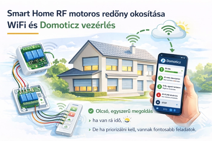
SmartHome RF motorized shutters are found in many households. Integrating these remote-controlled shutters into a smart home system, however, is not always straightforward, especially when you want to keep the existing motors, remote controls, and radio communication.
The solution presented here makes it possible to integrate existing SmartHome RF shutters into the Domoticz smart home system at relatively low cost, operating entirely over the local network without relying on cloud services.
It uses a SmartHome DC104 remote control, a four-channel Tasmota-compatible relay module, and Tasmota's built-in shutter control functionality.
Some SmartHome RF shutter motors use rolling-code radio communication. In these systems, commands cannot be reliably reproduced with a simple generic RF transmitter.
Instead of attempting to replace the radio protocol, this solution electronically simulates button presses on the original remote control.
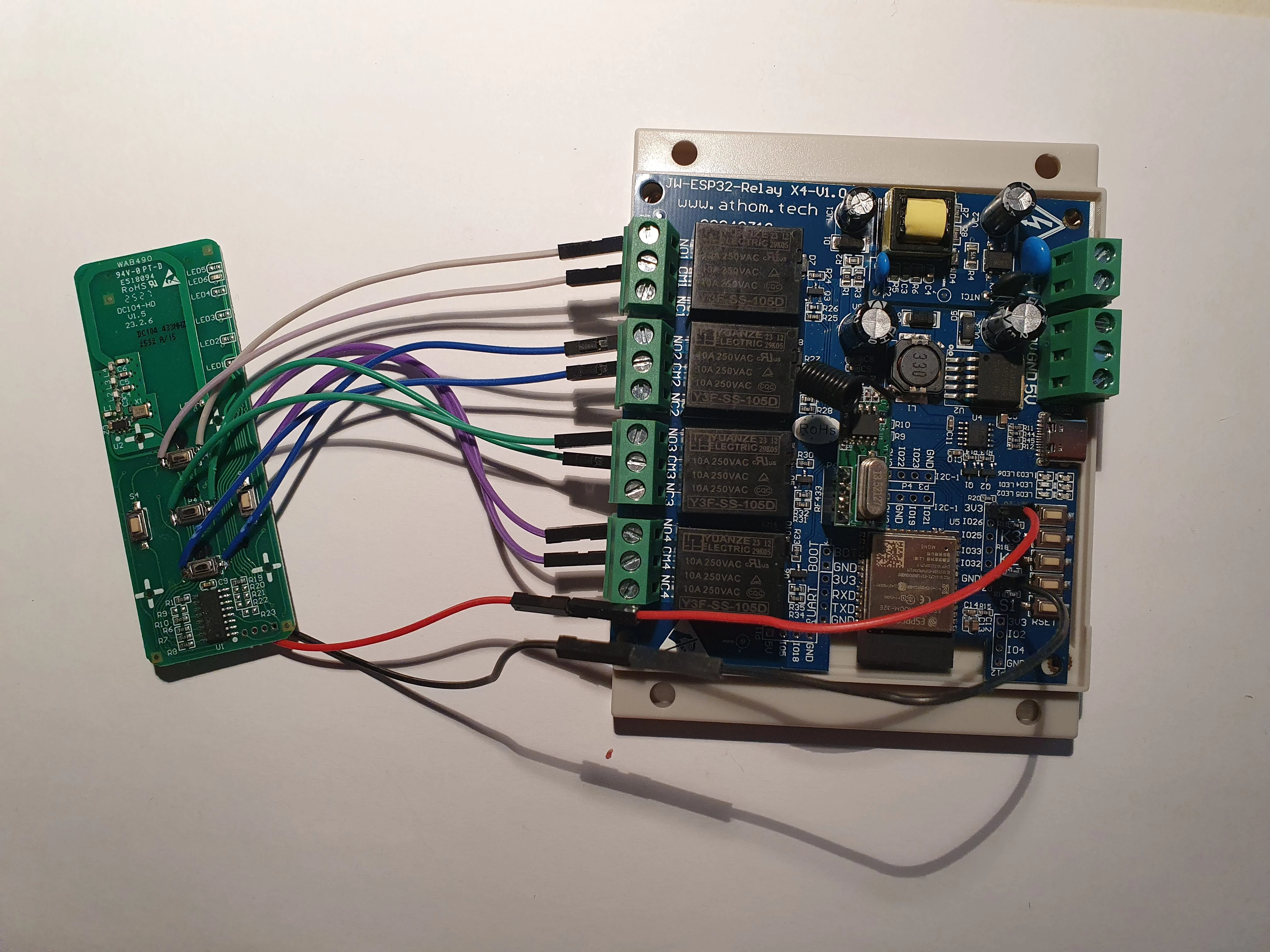
Small wires are soldered to the remote control's button contacts and connected to dry-contact relays. When a relay closes, it behaves as though someone has physically pressed the corresponding remote control button.
This approach preserves the original radio communication and pairing while enabling Wi-Fi control through the local network.
With the appropriate configuration, the shutters can also be integrated into Domoticz automation based on temperature, sunlight, presence detection, or the ASC automatic shutter controller.
The configuration demonstrated here was developed using an Athom four-channel relay module and a SmartHome DC104 remote control. GPIO assignments and wiring may differ with other hardware.
Opening the remote control provides access to the electrical contacts of its push buttons. By soldering thin wires to these contacts, the buttons can also be operated using external relays.
The solution uses four functions:
The relays momentarily connect the corresponding button contacts on the remote control. The dry-contact relay outputs must not apply external voltage to the remote control's button circuits.
| Function | Relay Channel | Connection |
|---|---|---|
| Up | Relay 1 | NO1 – COM1 |
| Down | Relay 2 | NO2 – COM2 |
| Stop | Relay 3 | NO3 – COM3 |
| Reset / Programming | Relay 4 | NO4 – COM4 |
In the original installation, the remote control is powered externally using its positive and negative power terminals.
Important: the remote control must only be supplied with a voltage that matches its electrical specifications. A 3.3 V supply is appropriate only if supported by the particular remote control. Verify the operating voltage before connecting an external supply.
If the relay module operates from mains voltage, proper separation between mains and low-voltage circuits, an appropriate enclosure, and adequate protection against electric shock are essential.
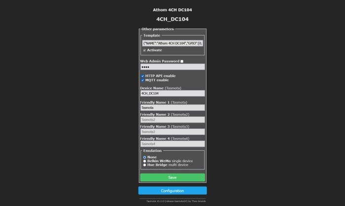
On first startup, Tasmota normally creates its own Wi-Fi access point. After connecting to it, the configuration interface is usually accessible at 192.168.4.1.
The following Tasmota Template was created for the Athom four-channel module used in this installation:
{"NAME":"Athom 4CH DC104","GPIO":[0,0,0,0,0,0,1,1,226,227,225,544,1,1152,0,0,0,0,0,0,0,224,0,0,0,0,0,0,34,35,32,0,0,33],"FLAG":0,"BASE":1}This template is specific to the GPIO configuration of the module used in this project. Do not apply it to a different relay module or hardware revision without verifying the pin assignments.
Enter the following commands individually in the Tasmota console:
Interlock 1,2 Interlock ON SetOption80 1 ShutterMode 1 ShutterRelay1 1 PulseTime3 10 PulseTime4 10These commands configure the following functions:
The first two relays operate the Up and Down buttons, the third relay operates Stop, and the fourth relay operates the programming button.
After restarting the relay module, verify that the Tasmota shutter functionality operates correctly. In the configuration shown, interlocking is required for correct operation of the first two relays in ShutterMode 1.
Recommended additional setting: the PowerOnState 0 command can be used to start with the relays switched off after a restart, reducing the risk of unintended button activation.
The following Tasmota Rule triggers the Stop button through the third relay when either the Up or Down relay is switched off.
Enter the complete rule as a single Rule1 command, followed by the activation command:
Rule1 ON Power1#State=0 DO Power3 ON ENDON ON Power2#State=0 DO Power3 ON ENDON Rule1 1The first command defines a rule responding to two relay events, while the second enables it.
Important: the combined behavior of ShutterMode, relay switching, and the Rule must be tested with the actual remote control. Tasmota also supports other types of motor control, so button press duration, Stop operation, and direction changes must be checked separately.
The original RF system does not necessarily provide actual position feedback to Domoticz. Tasmota therefore estimates shutter position using the configured movement times.
First, measure the time required for the shutter to travel fully upward and fully downward.
For example, if the shutter takes 32 seconds to open fully and 30 seconds to close:
ShutterOpenDuration1 32 ShutterCloseDuration1 30The correct values depend on the individual shutter and must be determined through measurement.
Movement times may vary depending on mechanical conditions. If the calculated position gradually differs from the actual shutter position, recalibration or synchronization at the end positions may be necessary.
Important limitation: Tasmota may not detect movement initiated using the original RF remote control. Consequently, the estimated position can differ from the actual position, including with bidirectional (BIDI) motors if their position feedback is not accessible to Tasmota.
You can configure a password for the Tasmota web interface using the following command:
WebPassword yourpasswordReplace yourpassword with a strong password of your own.
The web interface login username is generally admin.
Do not expose the Tasmota controller directly to the public internet. For remote access, use a secure VPN connection.
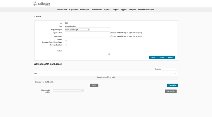
Three virtual Domoticz devices can be used to implement the control functions:
In the Tasmota Domoticz configuration interface, assign the same shutter device IDX to the first two relays. The third and fourth relays use separate virtual switches.
| Relay | Domoticz IDX | Function |
|---|---|---|
| Relay 1 | Shutter IDX | Up |
| Relay 2 | Same shutter IDX | Down |
| Relay 3 | Stop IDX | Stop |
| Relay 4 | Reset IDX | Programming |
Always use the actual IDX values of the devices created in your own Domoticz installation.
Communication between Domoticz and Tasmota also requires appropriate MQTT configuration.
To pair a SmartHome DC104 remote control with a shutter motor, follow the programming procedure specified by the motor and remote control manufacturer.
The following procedure was used in the installation described here:
Pairing procedures can vary between motor and remote control models. Some programming operations may also affect previously paired remote controls, so consult the manufacturer's documentation before proceeding.
Once integrated into Domoticz with percentage-based positioning, the shutter can also be controlled by ASC (Automatic Shutter Controller).
ASC determines the desired shutter position based on indoor and outdoor temperature, light intensity, and optional presence detection. Tasmota then moves the shutter using its time-based positioning function.
This allows a shutter that was previously operated only through its original RF remote control to become part of a locally managed smart home system without replacing the existing motor.
One of the main advantages of this approach is that the original remote control remains usable, while Domoticz and Tasmota communicate over the local network.
Experience with the original installation indicates that conventional non-BIDI RF motors can operate reliably with this approach. For bidirectional motors, compatibility depends on the particular motor and remote control combination.
The main limitation is the absence of true shutter position feedback. The percentage displayed by Tasmota is an estimate calculated from movement duration and may differ from the actual shutter position.
If network communication is interrupted, Domoticz automation may become unavailable. However, the original RF remote control can remain operational if the installation has been designed accordingly.
Integrating SmartHome RF shutters with Tasmota and Domoticz can provide a cost-effective alternative to replacing the existing motors or purchasing proprietary cloud-based controllers.
The main benefits include:
For further information about shutter control, see the official Tasmota Shutters and Blinds documentation.