

One of the fundamental objectives of the DSVT control system is to coordinate different heat sources and heating and cooling circuits within a single integrated system. However, proper hydraulic design is just as important as the control system itself.
The following schematic diagram was developed based on our own practical experience and consultations with specialists. It is not intended to serve as a detailed mechanical installation plan, but rather to illustrate a flexible hydraulic concept that can be used as a starting point for designing more complex systems.
We strongly recommend involving a qualified heating and HVAC engineer when designing the actual hydraulic installation. The heat source manufacturers' requirements, necessary flow rates, circulation pump operation, and all required safety and hydraulic components must be properly selected and sized for the specific equipment.
The proposed schematic is based on a common heating system configuration in which radiators and underfloor heating circuits operate together.
The diagram assumes a common supply water temperature of 50°C. Three-way motorised mixing valves can be used to reduce and regulate the supply water temperature according to the requirements of individual heating circuits.
This allows radiator and underfloor heating circuits to operate at different supply temperatures, while DSVT controls the associated equipment according to room heating demand and the selected control mode.
50°C is not a mandatory operating temperature. The actual supply water temperature depends on the building's heating demand, the design of the heat emitters, and the technical characteristics of the heat sources. In heat pump installations in particular, it is advisable to use the lowest possible supply water temperature that still provides adequate indoor comfort.
The following illustration shows the conceptual hydraulic arrangement of the system. A larger version of the diagram is available through Google Drawings.
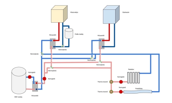
Open the hydraulic schematic diagram in full size
The proposed concept focuses on flexibility and a wide range of operating possibilities. However, this does not mean that every DSVT installation requires such a complex hydraulic arrangement.
For a simple single-zone heating installation, controlling just one heat source and one circulation circuit may be sufficient. In other cases, the desired control functions can be achieved with relatively minor modifications to an existing radiator or underfloor heating system.
The hydraulic configuration should always be selected according to the characteristics of the building and the functions actually required. Simpler arrangements may require fewer valves and control devices, although certain control capabilities may have to be sacrificed.
The modular architecture of DSVT allows the controller to be adapted to both simple and complex hydraulic installations.
