DSVT supports the control of two independent motorised mixing valves, allowing the supply water temperature of different heating and cooling circuits to be regulated.
This function is particularly useful in buildings with mixed heat distribution systems, where radiator heating and underfloor heating require different supply water temperatures.
During cooling operation, mixing valves can also control ceiling, wall, or floor cooling circuits, taking into account the appropriate temperature limits and dew point protection requirements.
Each mixing valve can operate with its own supply temperature sensor, target temperature, hysteresis, and control parameters.
DSVT compares the configured or calculated target temperature with the actual supply water temperature measured downstream of the mixing valve.
Depending on the difference between these values, the controller can:
Valve movement is controlled through the configured opening and closing outputs.
Rather than directly setting a percentage valve opening, DSVT uses feedback from the supply temperature sensor to control the motorised mixing valve.
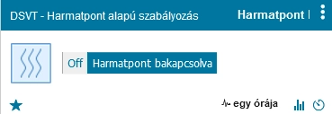
Two control methods are available during heating:
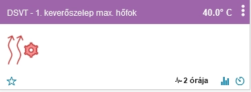
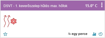
This parameter defines the maximum permitted supply temperature for the first mixing valve during heating operation.
The value should be selected according to the technical requirements of the connected heating circuit.
For example, an underfloor heating circuit generally requires a lower supply temperature than a conventional radiator circuit.
DSVT processes the configured value within the system's common minimum and maximum mixing valve temperature limits.
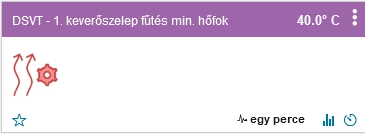
The minimum supply temperature defines the lower limit of dynamic heating control.
When the minimum and maximum temperatures are identical, the mixing valve attempts to maintain a constant target temperature.
When the values differ, DSVT calculates the supply temperature target between these limits according to heating demand.
During dynamic heating control, DSVT uses the difference between the heating target temperature and actual indoor temperatures.
The calculation is based on the difference between the system heating target and the lowest indoor temperature taken into account by the controller.
The greater this difference, the higher the requested supply temperature can become, within the configured minimum and maximum limits.
The calculated supply temperature is:
Target Temperature = Minimum + Ratio × (Maximum − Minimum)
The ratio is limited to a value between 0 and 1, ensuring that the calculated target remains within the configured temperature range.
The control slope of each mixing valve can be configured independently:
The default value is 100%.
At this setting, the controller reaches the configured maximum supply temperature when the indoor temperature difference reaches 1°C.
Reducing this value produces a steeper control response: a smaller indoor temperature difference is sufficient to request a higher supply temperature.
Increasing the value produces a more gradual response, requiring a larger indoor temperature difference before the maximum supply temperature is reached.
Consider the following settings for Mixing Valve 1:
In this case, the ratio is 0.5:
28 + 0.5 × (40 − 28) = 34°C
The calculated mixing valve target temperature is therefore 34°C.
If the indoor temperature difference increases further, the calculated target temperature also rises, but it cannot exceed the configured maximum supply temperature.
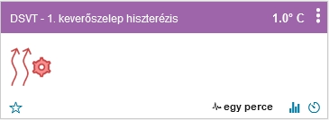
The purpose of hysteresis is to prevent the mixing valve motor from constantly changing position in response to small temperature fluctuations around the target.
DSVT compares the measured supply temperature with the calculated target and the configured hysteresis.
During heating operation:
For example, with a 35°C target temperature and 0.5°C hysteresis, no adjustment is required while the measured temperature remains between 34.5°C and 35.5°C.
Appropriate hysteresis settings reduce the frequency of valve movements and can help maintain a more stable supply temperature.
DSVT provides two control methods during cooling:
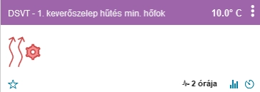
The minimum cooling temperature defines the lower target limit for normal cooling control.
Lower supply water temperatures can provide greater cooling capacity, but they can also increase the risk of condensation.
For this reason, particularly in radiant cooling systems, the value must be selected according to the technical and moisture-related limitations of the installation.
The maximum cooling temperature defines the upper target limit for dynamic control.
When the minimum and maximum temperatures are identical, the mixing valve attempts to maintain this constant supply temperature.
When the values differ, DSVT calculates an appropriate target based on the cooling target temperatures and measured indoor temperatures.
During cooling operation, a greater indoor temperature difference can result in a lower requested supply temperature.
The calculation is:
Target Temperature = Maximum − Ratio × (Maximum − Minimum)
The ratio varies between 0 and 1, ensuring that the calculated temperature remains within the configured range.
The control slope during cooling is also influenced by the S_1M and S_2M parameters.
Preventing condensation is particularly important in radiant cooling installations.
If the temperature of a cooled pipe or surface falls below the dew point of the surrounding air, moisture can condense on that surface.
Therefore, a properly designed radiant cooling system must take indoor temperature and relative humidity into account.
In dew point-based control mode, DSVT uses dew point values calculated from indoor temperature and humidity measurements to determine the mixing valve supply temperature target.
The controller uses the highest available indoor dew point when calculating mixing valve target temperatures.
This is because the room with the highest dew point presents the greatest condensation risk if the cooling surfaces become excessively cold.
The calculation is:
Supply Target Temperature = Highest Indoor Dew Point + Mixing Valve Compensation
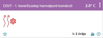
DSVT can apply a separate compensation value to each mixing valve, allowing the two cooling circuits to operate with different supply temperature targets.
The purpose of compensation is to maintain a cooling water target temperature above the highest calculated indoor dew point.
Important: the effectiveness of this protection also depends on whether valid temperature and humidity measurements from all relevant rooms are included in the calculation. An appropriate safety margin, actual surface temperatures, and sensor reliability remain important.
DSVT's software-based dew point control does not replace proper moisture-related engineering design, condensation sensors, or any required hardware safety protection.
DSVT provides a separate dew point compensation value for each mixing valve.
This allows the supply temperature target to be set above the highest calculated indoor dew point.
For example:
The calculated supply temperature target is:
20°C + 3°C = 23°C
Higher compensation generally reduces cooling capacity but can increase the safety margin against condensation.
The appropriate value should be selected according to the design of the cooled surfaces, pipe insulation, indoor humidity conditions, and operating characteristics of the installation.
In some installations, cooling may not be required in a circuit equipped with a mixing valve.
By setting a sufficiently high supply temperature target, the mixing valve can be controlled in a direction that reduces cooling output.
However, this is not equivalent to safely isolating a hydraulic circuit.
If complete isolation of a cooling circuit is required, a suitable motorised shut-off valve or another appropriately designed hydraulic solution must be used.
The following parameters can be configured separately for each mixing valve:
For example, one mixing valve can control an underfloor heating and cooling circuit, while the other can control radiator heating or ceiling cooling.
Correctly installed supply temperature sensors and suitable control outputs for the motorised valves are required for proper operation.
Proper mixing valve operation requires not only correct software configuration but also an appropriately designed hydraulic system.
Particular attention should be paid to:
Software-based temperature limiting does not replace independent safety devices required by the heat source or heat distribution system manufacturer.
DSVT supports the control of two independent motorised mixing valves, allowing supply water temperatures to be regulated for different heating and cooling circuits.
During heating, either constant or dynamically calculated target temperatures can be used according to indoor heating demand.
During cooling, the target temperature can vary between configured minimum and maximum values or be calculated according to indoor dew point conditions.
In dew point-based cooling mode, DSVT uses the highest available indoor dew point and adds the compensation configured separately for each mixing valve.
Individually adjustable control slopes, hysteresis, and dew point compensation allow mixing valve operation to be fine-tuned.
Properly configured mixing valve control can improve coordination between different heating and cooling circuits, enhance comfort, and support more energy-efficient operation, while dew point-based control can help reduce the risk of condensation.